OPTICS AND OPTICAL MEASUREMENT INSTRUMENTS
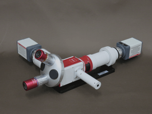
NFP/FFP SIMULTANEOUS MEASUREMENT OPTICS M-Scope type D
PRODUCT OVERVIEW

M-Scope type D realizes simultaneous observation and analysis of NFP and FFP by a single optical unit.
Previously, for measurement and analysis of NFP and FFP, dedicated two kinds of optics, NFP measurement optics and FFP measurement optics, are needed. M-Scope type D realized simultaneous observation and analysis of NFP and FFP without changing optics by using specially designed single optical unit.
By selecting imaging detector, it will be applicable for optical beam profile observation and analysis from 400~1700nm wavelength range.
It is also possible to construct the NFP/FFP simultaneous measurement system by combining with various imaging detectors and Synos' Optical Beam Analysis Module AP013.
FEATURE
- Realizes simultaneous observation and analysis of NFP and FFP by a single optical unit.
- Realtime observation and analysis with special optics and image processing
- By selecting the imaging detector, it will be applicable for optical beam profile observation and analysis in 400~1700nm wavelength range
- In combination with SYNOS' Optical Beam Analysis Module AP013, it will be applicable to various optical beam profile analysis application.
APPLICATION
- Beam pattern and emitted beam angular evaluation of various LDs, fibers, waveguides, etc.
- Lens position, angle alignment and evaluation of visible-NIR LD modules
- Collimator and focusing lens alignment and evaluation of various butterfly package devices and modules
- Collimator and focusing lens alignment and evaluation of various butterfly package devices and modules
- Evaluation of various waveguide such as polymer optical waveguides for OPCB substrate, Si photonics waveguides, etc.
- Research and development, assembly adjustment of special optical devices and optical modules
SUMMARY OF SPECIFICATION
MAIN SPECIFICATION OF THE OPTICS
| NFP measurement port | ||
|---|---|---|
| Objective lens switching | Manual revolver (mounting maximum 4 objective lenses) | |
| Objective Lens | M-Plan Apo NIR 50x (fixed during NFP/FFP measurement) *M-plan Apo series objective lens can be used only for NFP measurement function |
|
| Intermediate lens | 1x (standard), 2x (option) | |
| Total magnification | standard:50x (with a 50x objective lens, NFP/FFP simultaneous measurement) option:100x (Using an optional 2x intermediate magnification lens and objective lens with 50x) |
|
| Coaxial epi-illumination port | option: coaxial epi-illumination port (for tip diameter φ8mm port light unit), coaxial epi-illumination system | |
| Optical attenuation method | by neutral density filters | |
| Camera mount | C mount | |
| FFP measurement port | ||
| Objective lens for NFP/FFP simultaneous measurement | M-Plan Apo NIR 50x (fixed) | |
| Measurement angle coverage | approx. ±24.5° | |
| Pixel resolution | High Resolution CMOS Detector ISA071/ISA071GL | approx. 0.037° |
| InGaAs High Sensitivity NIR Detector ISA041H2 | approx. 0.2° | |
| W.D. | approx. 17mm | |
| Optical attennuation method | by neutral density filters | |
| Camera mount | C mount | |
SIMPLE STRUCTURE OF NFP/FFP SIMULTANEOUS MEASUREMENT OPTICS M-Scope type D

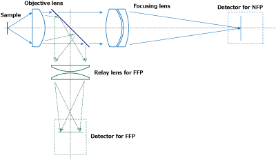
In M-Scope type D, FFP is measured using objective lens. In the figure on the left, the luminous flux emitted from the emitting point is incident on the objective lens and then the optical path is split by the half mirror. The light flux that has passed through the half mirror advances to the NFP port side and is imaged on the NFP measurement detector via the focusing lens. On the other hand, the light flux reflected by the half mirror advances to the FFP port side and is imaged on the FFP measurement detector via the FFP relay lens. In this way, NFP and FFP images obtained from each port branched into two optical paths are analyzed by image processing, and NFP/FFP measurement are realized with a single optical unit.
Since this optics uses objective lens to measure NFP/FFP, the diameter of the light flux to be measured is very narrow (about 100 μm), it is necessary to adjust the position and focus on the NFP image. Additionally, the measurement wavelength is limited because appropriate AR coating is required for optical path splitting half mirror of NFP/FFP port. These are major differences from the FFP measurement method using f-θ lens.
COMPONENT
STANDARD COMPONENT
- M-Scope type D (optics unit including NFP measurement port, FFP measurement port, manual revolver) : 1set
- Base plate for optics : 1set
OPTION
- Intermediate lens port
- 2× Intermediate Port MS-OP011-RL2
- Intermediate lens unit that doubles the overall magnification of the optical system. (up to 200× with 100× objective lens)
- 1/2× Intermediate Port MS-OP011-RLH
- Intermediate lens unit that halves the overall magnification of the optical system.
- Coaxial Epi-illumination Port MS-OP011-CEP
- Coaxial epi-illumination port with removable half mirror.
- Objective lens selection
- Only M-Plan Apo Series 50x can be used for NFP/FFP simultaneous measurement .
- About objective lens selection for NFP measurement function, please refer to here.
- Detector selection
- Wavelength range : 400~1100nm
- Wavelength range : 950~1700nm
- About imaging detector selection, please refer to here.
- Neutral density filter
- About neutral density filters, please refer to here.
- Coaxial epi-illumination unit
- About coaxial epi-illumination units, please refer to here.
- Optics workbench for sample measurement
- Optics Bench For Fiber Measurement OP002-F3/OP002-F5
- Vertical Type Optics Bench OP002
- About optics workbench, please refer to here.